
General arrangement:
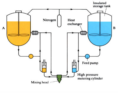
Schematic outline of mixing apparatus for RIM. Component A (polyol) and component B (isocyanate) are continuously circulated under a nitrogen blanket through the mixing head.
Low molecular weight monomers polymerise in the mould. RRIM has reinforcement added to the monomer.
Piston operation of the RIM mixing head: (a) in the closed position there is no contact between continuously circulating streams: (b) impingement mixing of A and B streams occurs when the piston is withdrawn.
Manufacture:
- An economic alternative to injection and compression moulding, particularly large surface area components, due to low capital costs and energy requirements. RIM equipment costs approximately 30% less than comparable injection moulding equipment, and product energy requirements are low compared with other materials, although RRIM would increase these.
- Critical process variables are mould and monomer temperatures, injection and clamping pressures, material flow rate and density. Close control of these variables is an essential part of the process, lending itself readily to CAM and robotics. Processing parameters vary with material.
- Clamping force depends on material and projected area of component, but can be as low as 0.4 MPa and is at least an order of magnitude less than for injection and compression moulding.
- Low injection and clamping forces are due to the low viscosity of the monomer mixture, enabling the use of vertical machines, saving floor space considerably, and moulds of aluminium, zinc alloy or even epoxy for small production runs and prototypes.
- Cycle times depend on material and component size and shape, but are comparable with injection moulding for small parts. Above 0.5 kg RIM is better than injection moulding; for a 5 kg part a 1 min part-to-part demould time is typical.
- A PTFE or silicone wax mould-release agent (MRA) was necessary before each cycle, but in-mould release (IMR) technology has recently resulted in a 50% increase in productivity by including MRA in the monomer mixture before injection.
- To eliminate secondary painting, U.V.-stable pigments can be added to the monomers, or pigmented PUR coatings can be sprayed into the mould before injection.
- RIM and RRIM are used mainly for fascias, bumpers, body panels and steering wheels for the automotive industry, although the processes are making inroads into the furniture industry.
Typical RIM processing parameters:
|
Material |
Monomer processing temperature (˚C) |
Mould temperature (˚C) |
Injection pressure (105 Pa) |
|
Urethane |
32 - 49 | 77 - 93 | 103 - 207 |
|
Nylon |
71 - 129 | 129 - 138 | 14 - 55 |
| Epoxy | 38 - 71 | 93 - 149 | 34 - 103 |
Materials:
- At present, polyurethanes, epoxy and polyester.
- The most common reinforcement material is 1.6 mm hammer-milled glass, but flaked glass, 1.5 mm chopped strand glass, mica, wollastonite and fibres of nylon, carbon, and polypropylene are currently under investigation.
Material properties of RRIM systems:
| Property | Urethane, high modulus | Nylon 6 | Epoxy |
| Glass content (%) | 23* | 25* | 45 - 52† |
| Tensile strength (MPa) | 45 | 52 | 193 - 303 |
| Elongation (%) | 14 | 13 | – |
| Flexural modulus at 24˚C (MPa) | 2620 | 1896 | 17,927 - 25,511 |
|
Coefficient of linear thermal expansion (parallel to fibres) (× 10-6 ˚C-1) |
45 | 52 | – |
*1.6 mm milled glass; † continous glass.
Design:
- Similar to injection moulded components, although larger surface areas, in excess of 2 m2, and thinner sections can be produced. Blind holes and extreme variations in wall thickness should be avoided wherever possible.
- Several components can be combined in one large die.
- Part shrinkage occurs in the mould, the amount depending on the material (e.g. 1% for nylon) and allowances must be made for this in die design.
- Good surface finish can be obtained, depending on the condition of the mould.
- Components of up to 45 kg are currently being produced.
- Components can be coloured using pigments or pigmented mould coatings, but only for parts that do not require colour matching, such as automobile interiors.
See Also: Injection moulding, Compression moulding and High pressure die casting.
This article is a part of Manupedia, a collection of information about some of the processes used to convert materials into useful objects.
Rate and Review
Rate this article
Review this article
Log into OpenLearn to leave reviews and join in the conversation.
Article reviews