
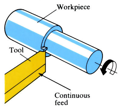
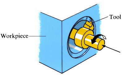
Turning
Cylindrical turning on an engine lathe
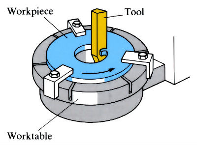
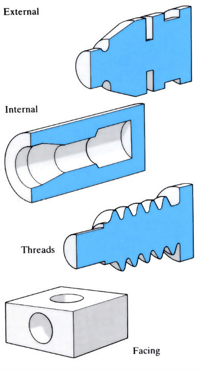
Boring
Facing on a vertical boring machine
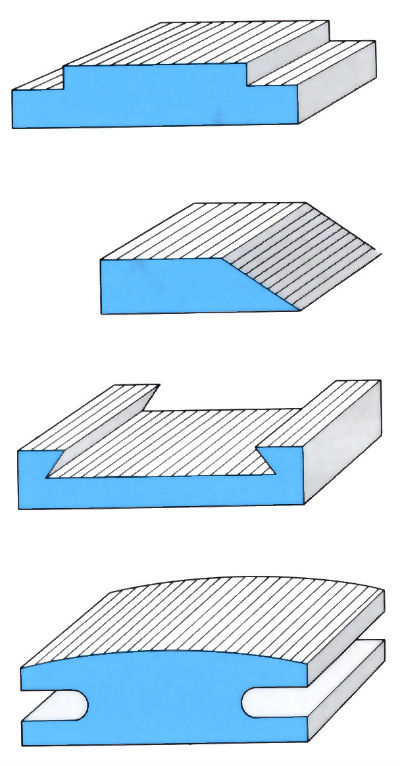
Planning/shaping
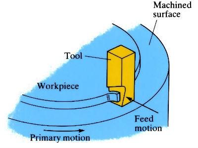
Internal boring on a horizontal boring machine
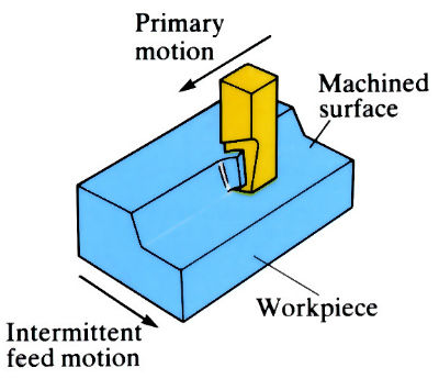
Production of a flat surface on a shaper
Manufacture:
Turning
- Most extensively used machining process, carried out on a wide range of lathes from the simplest engine lathe to the most complex multi-spindle NC lathe.
Boring
- Machines can be horizontal or vertical, and are used mainly for heavy, large diameter workpieces that cannot be turned on a lathe.
Planning/shaping
- Machines are usually horizontal, and process is slow since 2/5 of the time is spent on the return stroke. Largely replaced by milling.
Materials:
- Single point cutting can be carried out on almost any material whose hardness is less than that of the cutting tool material.
- Economic machining of a material depends on many factors: hardness of material, hardness and toughness of cutting tool, design of cutting tool, cutting fluid, metal removal rate, surface finish, tolerance, feed, speed, etc.
Design:
Turning
- Mainly for producing cylindrical (turning), flat (facing) or shaped (tapers, threads, etc.) surfaces.
- Tolerances vary from ±0.5 mm (rough turning) to ±0.1 mm (fine turning).
- Roughness varies from 25 µm Ra (rough turning) to 0.05 µm Ra (fine turning), but is typically 0.5–5 µm Ra.
Boring
- Mainly for facing, hole cutting and enlarging/truing drilled or turned holes in large components.
- Tolerance and roughness as for turning.
Planning/shaping
- Mainly for roughing and finishing flat surfaces, although arcs and special forms can be generated.
- Shapers used for smaller components than planers.
- Tolerances are typically ±0.05–0.1 mm.
- Roughness varies from 50 µm Ra (roughing) to 0.5 µm Ra (finishing), but is typically 1–25 µm Ra.
See Also: Multipoint cutting, Grinding and Creep feed grinding.
This article is a part of Manupedia, a collection of information about some of the processes used to convert materials into useful objects.
Rate and Review
Rate this article
Review this article
Log into OpenLearn to leave reviews and join in the conversation.
Article reviews