
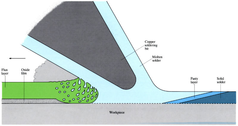
Principle of soldering and action of suitable flux
- Mating surfaces are degreased and pickled before soldering.
- Components are assembled or jigged as necessary.
- Surfaces to be soldered are coated with flux to dissolve any remaining oxide films, and to promote wettability.
- Copper soldering bit heats the solder and conveys solder to the workpiece. In mass production, various forms of heating are used, including "vapour-phase" soldering.
Manufacture:
- Surface preparation – degreasing using organic solvents and/or alkaline solutions. Abrasive cleaning and pickling to remove oxide films.
- Assembly/jigging (see Brazing L01) – where possible joints should be self-locating.
- Heating – mass soldering uses the molten solder as a heat source to melt the pre-coated flux. Direct coating uses a separate heat-conducting source: soldering iron, hot plate or hot-oil immersion. Non-contact methods use ovens, gas burners and induction heating. Comparison of heating methods:
- Flame: low cost and output, highly versatile, hand-feed systems
- Electrical resistance: medium cost and output, poor versatility, preforms required
- Radio-frequency induction: high cost and output, preforms required
- Dipping bath: medium cost, low output and versatility
- Soldering iron: hand-feeding gives low cost and output, but high versatility
- Finishing – flux and residual solder are removed before inspection.
Materials:
- Metals that do not readily oxidise (Sn, Cu, mild steel, Ni Au and Ag) are most easily soldered.
- Solders usually contain tin to promote surface wetting. Special solders with melting points up to 365˚C are available.
| Grade | % Tin | % Lead | % Antimony | Melting range (˚C) | |
| A | 64 | 36 | - | 183 - 185 | |
| K | 60 | 40 | - | 183 - 188 | |
| F | 50 | 50 | - | 183 - 212 | |
| R | 45 | 55 | - | 183 - 224 | |
| G | 40 | 60 | - | 183 - 234 | |
| H | 35 | 65 | - | 183 - 244 | |
| J | 30 | 70 | - | 183 - 255 | |
| V | 20 | 80 | - | 183 - 276 | |
| W | 15 | 85 | - | 227 - 288 | |
| B | 50 | 47 | 3 | 185 - 204 | |
| M | 45 | 52.3 | 2.7 | 185 - 215 | |
| C | 40 | 57.6 | 2.4 | 185 - 227 | |
| L | 32 | 66.1 | 1.9 | 185 - 243 | |
| D | 30 | 68.2 | 1.8 | 185 - 248 | |
| N | 18 | 80.9 | 1.1 | 185 - 275 | |
| Uses | BS 219 grades | ||||
| Electrical |
General electrical soldering (by hand) Printed-circuit mass-soldering Electric-lamp bases Electric cable conductors Wiped joints on lead cable-sheath |
K, F A, K V, W H, J L, D |
|||
| General Engineering |
General sheet-metal work (steel, copper, tinplate) General sheet-metalwork (brass, galvanised sheet) |
K, F, R, G, B, M, C K, F |
|||
| Automotive |
Heat-exchangers, automotive radiators, refrigerators Auto-body patching and filling |
G, J C D |
|||
| Others |
Capillary plumbing joints Dip-soldering (non-electrical) Coating (pre-tinning) Food-can soldering |
K, F, G C, D, N K, G K, F, G |
|||
Design:
- Optimum gaps are 0.08–0.18 mm. Below 0.08 mm vapour may be trapped, over 0.18 mm no capillary action.
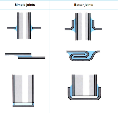
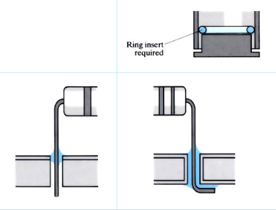
- Lap joints are essential.
- Additional mechanical strength is possible.
- Solder preforms (BS 1723) affect joint shape.
- Designs for soldering components onto printed circuit boards, depend on the strengths required.
See Also: Adhesive bonding, Brazing and Fasteners
This article is a part of Manupedia, a collection of information about some of the processes used to convert materials into useful objects.
Rate and Review
Rate this article
Review this article
Log into OpenLearn to leave reviews and join in the conversation.
Article reviews