
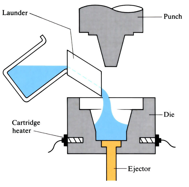
Stage 1
Die set positioned on hydraulic press, preheated to 200–250°C and coated with a releasing agent such as graphite. Accurate metering of liquid metal into die cavity via a "launder".
Stage 2
Press actuated to bring two parts of die set together. Metal displaced to fill die cavity and pressure held until solidification is complete.
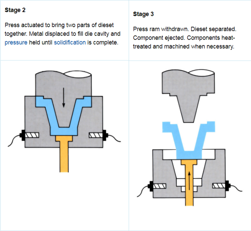
Stage 3
Press ram withdrawn. Die set separated. Component ejected. Components heat-treated and machined when necessary.
Manufacture:
- An alternative to gravity and high pressure die casting and forging for low cost, high strength aluminium alloy components.
- Only requires one die set and operates at lower pressures than forging, in the range 30–110 MPa depending on component geometry and material.
- Runner and feeder systems not usually required, giving high metal yields and weight tolerances of ±2%.
- Solidification times less than other casting processes except high pressure die casting and “Hyperforge” process.
- Accurate control of all process variables makes process difficult to operate under production conditions and often leads to slow cycle times. Typical production rates are 5–30 shots h-1.
- Final machining is kept to a minimum.
- Typical products include wheels, hubs, pistons, etc. for the automotive and aerospace industries.
Materials:
- To date only aluminium casting and forging alloys are used commercially, but there is no reason why the process cannot be used with most metals and alloys.
- Secondary quality aluminium casting alloys can be used without coarse iron aluminide needles impairing mechanical properties.
- Process produces a fine grain structure (typically 120 μm) with small dendrite cells (typical arm spacing 20 µm).
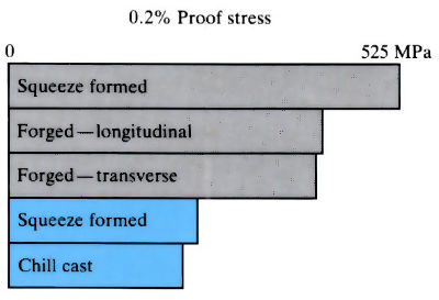
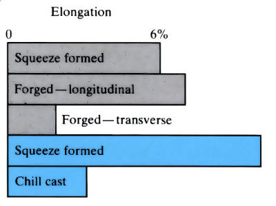
- Tensile properties of casting alloys better in all respects than conventionally cast material.
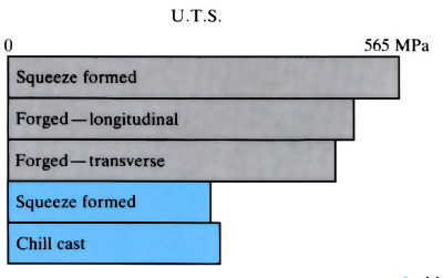
- Tensile properties of squeeze formed components compare favourably with those of conventionally forged components.
- Unlike forging, squeeze forming produces isotropic properties with ductilities between that of longitudinal and transverse forgings.
- Fatigue properties of squeeze formed components compare favourably with forged components, but are superior to chill cast.
Tensile data for casting LM25 and forging 7075 alloys, solution treated and aged to maximum strength.
Design:
- Weight range 2–50 kg, depending on press capacity.
- Thickness range 3–50 mm.
- Uniform thickness preferred to give uniform solidification and minimise residual stresses and porosity.
- Careful design enables porosity to be “manipulated” to the least critical regions.
- External undercuts are possible.
- Complex internal shapes possible using disposable cores.
- Blind and through holes easy to incorporate; lateral holes by means of retractable cores.
- Tolerances of 0.2 mm 100 mm-1 possible before heat treatment. Wider tolerances advisable to allow for distortion during subsequent heat treatment and to minimise costs.
- Tolerances across part line should be least 0.25 mm 100 mm-1.
- Surface finish depends on material and die condition, but is usually in the range Ra= 0.4–3.2 μm
- Inserts can be incorporated into components to improve properties in critical areas, e.g. fibre reinforced Al2O3 pads in piston heads.
See Also: High pressure die casting and Hot forging (closed die).
This article is a part of Manupedia, a collection of information about some of the processes used to convert materials into useful objects.
Rate and Review
Rate this article
Review this article
Log into OpenLearn to leave reviews and join in the conversation.
Article reviews