

7 Types of hydro turbine
Present-day hydro turbines come in a variety of shapes (Figure 17). They also vary considerably in size, with ‘runner’ diameters ranging from as little as a third of a metre to some 20 times this. Here we look at how they work, the factors that determine their efficiency, and the site parameters that determine the most suitable turbine.
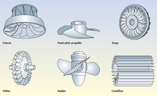
Francis turbines (figure 17, top left) are by far the most common type in present-day medium- or large-scale plants, being used in locations where the head may be as low as 2 m or as high as 200 m. They are radial-flow turbines, which means the water flow is inwards towards the centre, and modern turbines can achieve efficiencies as high as 95% – but only under optimum conditions, as maintaining exactly the right speed and direction of the incoming water relative to the runner blades is important.
‘Propeller’ or axial-flow turbines (figure 17 top centre) sweep their blades through the entire area which the water enters, and are therefore suitable for very large volume flows and have become usual where the head is only a few metres. In such turbines the efficiency can be improved by varying the angle of the blades when the power demand changes. Kaplan turbines (figure 17 bottom centre) are axial turbines where the blade angle may be varied to improve efficiency.
Pelton Wheels (figure 17 bottom left) are the preferred turbine for sites of the type shown in Figure 5.14 (c) with heads above 250 metres or so. The pelton is in contrast to the reaction turbines discussed above, it is an impulse turbine, operating in air at normal atmospheric pressure, and is basically a wheel with a set of double cups or ‘buckets’ mounted around the rim. The water passes round the curved bowls, and under optimum conditions gives up almost all its kinetic energy. The power can be varied by adjusting the jet size to change the volume flow rate, or by deflecting the entire jet away from the wheel.
Turgo turbines (figure 17 top right) are a variant on the Pelton wheel, where the double cups are replaced by single, shallower ones, with the water entering on one side and leaving on the other. This is still an impulse turbine, but is able to handle a larger volume of water than a Pelton wheel of the same diameter gives it an advantage for power generation at medium heads.
The cross-flow turbine (figure 17 bottom right) is another impulse type. The water enters as a flat sheet rather than a round jet. It is guided on to the blades, travels across the turbine and meets the blades a second time as it leaves.