
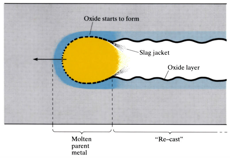
Cutting reaction zone and drag lines
Primary reaction: Fe+O→FeO+heat
Secondary reaction: 3Fe+2O2→Fe3O4+heat
Elevation

The cutting torch has an oxygen jet surrounded by heating flames.
900cm3 of oxygen is required to oxidise 0.5 kg of iron. This principle has been designed into a welding torch. A jet of high-pressure oxygen in the centre is surrounded by several neutral flames. When the metal becomes cherry red in colour, at 800°C, the oxygen is released by a quick acting valve. The quality of the cut is governed by the oxygen vent size, oxygen pressure, cutting speed and pre-heating flames.
Plan
Manufacture:
- A small amount of metal is pre-heated to the oxygen ignition temperature using a pre-heating flame, and a stream of high purity oxygen is impinged on the heated area. The oxygen ignites the metal and oxidises it in a narrow section which becomes the kerf as the molten metal and oxide are removed by the kinetic energy of the oxygen stream.
- The pre-heating flame is usually oxy-acetylene, but other cheaper gases such as propane, or natural gas can be used.
- Oxygen purity should be >99.5% since a 1% decrease in purity increases consumption and decreases cutting speed by 25%. Cutting will not occur below 95% purity.
- Cutting speeds are very dependent on oxygen pressure and nozzle design. Increased oxygen pressure and high performance nozzle design can increase cutting speeds by 30%. The higher pressures can not only result in higher cutting speeds, but also more efficient slag ejection, at 0.4 m3 h–1 of acetylene.
- Pressures of over 10 MPa have been used, but the small increase in cutting speed is out of proportion to the unacceptable high noise and dust generation.
- Process can be adapted to give increased cutting speeds and to cut non-oxidisable materials by using powder cutting, in which an iron-based powder is injected into the oxygen stream.
- Cutting torches can be hand-held, but are frequently used in conjunction with high precision, numerically controlled guiding machines.
- Production rates depend on material thickness and composition, nozzle design, oxygen pressure and purity and “quality” of cut required. Production rates can be improved by “stock cutting” and the use of multiple torches.
- Mainly used for the weld edge preparation of steel plate, but also used for profiling and the production of ring gears and moulds.
| Standard nozzle | High performance nozzle | ||||||
|
Thickness (mm) |
O2 (MPa) |
O2 (m3 h-1) |
v (mm min–1) |
O2 (MPa) |
O2 (m3 h-1) |
v (mm min-1) |
∆v (%) |
| 10 | 0.4 | 2.8 | 620 | 0.8 | 3.2 | 725 | 17 |
| 40 | 0.5 | 3.3 | 340 | 1.0 | 4.7 | 460 | 35 |
| 100 | 0.6 | 10.0 | 250 | 1.1 | 10.6 | 280 | 12 |
Note: O2 (MPa); oxygen pressure required at torch; O2 (m3 h-1), total oxygen consumption: v (mm min-1), cutting speed; ∆v (%), percentage increase in cutting speed achieved by high performance nozzle.
Materials:
- Materials with the following properties can usually be successfully flame cut:
- easily oxidisable at pre-heating temperature
- high heat of combustion
- melting point of oxides below melting point of workpiece
- low viscosity oxide
- low thermal conductivity
- “ignition temperature” (Tign) of material below its melting point
(Tign is the temperature at which the reaction heat released = heat conducted away; i.e. above Tign combustion is self-sustained.)
- As a result of these requirements, normal flame cutting is usually confined to low carbon and low alloy steels. Most non-ferrous metals cannot be flame cut, although titanium, which does not fulfil the above requirements, can be successfully flame cut.
- Despite precautions, carburisation and hardening usually occur in the thin solidified “re-cast” layer.
- High alloy steels, cast irons and non-ferrous metals cannot usually be cut by conventional flame cutting and require “powder cutting” or plasma arc cutting.
Design:
- Used mainly for cutting and profiling sheet and plate.
- Main use is for a variety of weld edge preparations.
- U-profiles, for single and double U-butt welding of thick plate, can be produced using the “Longcave” technique.
- Material thickness depends on nozzle design, oxygen pressure and material composition, but is typically 1.5–50 mm. Thicknesses as small as 0.75 mm and as large 2500 mm have been successfully flame cut.
- Kerf widths depend on thickness of material and diameter of cutting jet, but are of the order of twice the jet diameter. Kerf width control of ±0.5 mm is possible up to 50 mm thickness.
- Cross-sectional squareness of ±1.5 mm can be obtained in steel of 150 mm thickness, cuts in thinner sections being held within proportionally smaller limits.
- Flame cutting is capable of producing cut edges with a smoothness comparable with metal cutting machine tools, i.e. peak to valley height 25–250 µm.
- “Drag lines” on the surface of the cut face are inherent to flame cutting, and under ideal cutting conditions it is these drag lines which determine surface roughness.
- Dimensional control of flame cut sheet and plate is largely dependent on accuracy of profiling equipment and the thermal expansion of the material.
See Also: Plasma arc cutting, Water jet cutting, Abrasive jet cutting, Laser cutting and Electrical discharge wire cutting.
This article is a part of Manupedia, a collection of information about some of the processes used to convert materials into useful objects.
Rate and Review
Rate this article
Review this article
Log into OpenLearn to leave reviews and join in the conversation.
Article reviews