
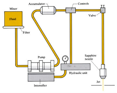
Cuts material by the impingement of a high velocity water jet against the workpiece. Relatively small volumes of water are used at high pressures, which are produced by a pump and intensifier with an accumulator tank to smooth out the pressure pulses.
Manufacture:
- An alternative to abrasive jet cutting, laser cutting, electron beam cutting, plasma arc cutting, EDWC, flame cutting and fine blanking for cutting and profiling sheet materials.
- Cutting medium is water with additives to aid coherence of the jet stream, reduce noise and prevent freezing. The jet has a velocity of 5–15 m s-1, a flow rate of up to 75 l min-1 and produces a force of 5–135 N on the workpiece. Pressure of jet varies from 70 to 415 MPa; the greater the pressure, the greater the penetration and quality of cut but the more power required. Up to 40 kW may be needed for the pumps, and the power density of the jet can reach 107 kW m-2.
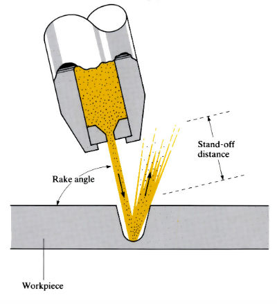
- Nozzles are usually of sapphire, but hardened steel and stainless steel are also used. Nozzle diameters vary from 0.075 to 0.40 mm. The smaller the nozzle, the finer the cut, but larger nozzles are required for thicker materials. Increasing the nozzle diameter increases performance, but also increases power requirements. Nozzle life depends on the purity of water used, but is excellent if the water is demineralised, deionised and filtered to 0.5 µm. Rake angles vary from 0˚ to 30˚, positive rake angles usually improving cutting performance. Stand-off distance depends on material type and thickness, cutting speed and edge quality. Distances vary from 2.5 to 50 mm, with 5 mm being typical. The greater the stand-off distance, the more the noise and less the penetration.
- Cutting speeds depend on material type and thickness, but are directly proportional to power and inversely proportional to thickness. The slower the cutting speed, the better the quality of the cut. Cutting speeds of up to 30 m s-1 have been achieved with paper, but can be as low as 2.5 mm s-1 on fibreglass.
- Thick materials may need multiple passes which, although reducing cutting speed, have the advantage of using less overall energy per unit length of cut.
- Since there is no force perpendicular to the water jet and very little frictional drag in the cut, accurate fixing and positioning of the workpiece is easy.
- Single or multiple cutting heads can be used, and positioning can be by hand, CNC or optical tracing.
Materials:
- A wide variety of materials, but most suitable for non-metallic materials and thin, soft metals such as Al, Cu, Pb and mild steel. Materials currently cut include plastics, composites, wood, paper, asbestos, leather, fabric, food and ceramics.
- Hard metals have not been successfully cut, but hard, dense, glass-like materials such as acrylics, polycarbonates and styrene do not cut well except in thin sheets.
- Laminated composites have a tendency to delaminate, but this can usually be avoided by reduction of cutting rate and careful control of cutting variables.
- Very little heat is generated, so there is no thermal distortion and/or HAZ. The high energy density of the jet stream can cause a slight temperature rise which may lead to melting of some plastics, particularly at slow cutting rates.
Design:
- Thickness of material which can be cut depends on the material itself, the cutting rate and the quality of cut, but varies from tissue paper up to 250 mm of foam rubber.
- Kerf width is 0.025 mm greater than the nozzle diameter, and is not affected by dwell time. This means that the accuracy of contours is limited only by the positioning of the workpiece and/or cutting head, not by the water jet nozzle. The minimum radius possible is approximately half the kerf width.
- A slight taper is produced, which increases with stand-off distance and material thickness. A positive rake can eliminate taper on the workpiece.
See Also: Abrasive jet cutting, Laser cutting, Plasma arc cutting, Electrical discharge wire cutting (EDWC) and Flame cutting.
This article is a part of Manupedia, a collection of information about some of the processes used to convert materials into useful objects.
Rate and Review
Rate this article
Review this article
Log into OpenLearn to leave reviews and join in the conversation.
Article reviews