
Manufacture:
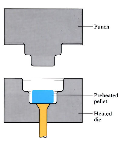
- A female mould impression is filled with a pre-weighed amount of thermosetting powder mix or a pre-formed pellet.
- The charge is usually preheated to 60–100˚C using an oven or high-frequency induction heater. The mould is heated to 140–170˚C and the temperature may increase further due to the exothermic nature of cross-linking.
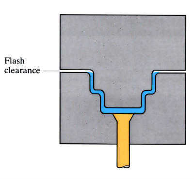
- A compressive pressure of 14–40 MPa is applied to the charge with a top male punch at shear rates of 1–10 s-1. This allows the material to flow into the required shape.
- Compressive moulding is a low shear process and minimum flow patterns are used.
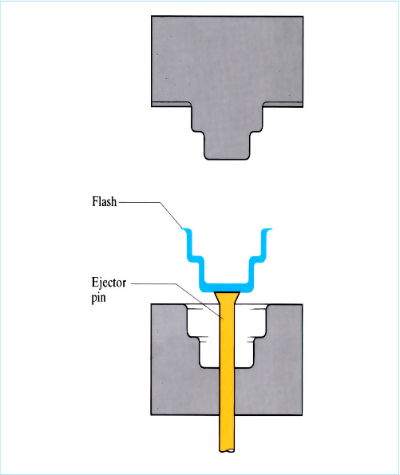
- Curing also occurs under the influence of heat and pressure (cure times vary between 0.5 and 3 min). This reduces the production rates compared with injection moulding.
- Scrap rates (2–5%) are lower than with injection moulding because there are no sprues or runners.
- Tool costs are high, but this is offset by low die wear at the low shear forces involved.
- Low product shrinkage (<1%).
- Process gives repeatable precision forming.
- Metal inserts and threads can be moulded-in.
Materials:
- Use is restricted to thermoset polymers as follows:
phenol-formaldehyde
urea-formaldehyde
epoxy resins - Fillers are added for dilution or reinforcement, e.g. woodflour, cotton, glass, mica or talc.
- Phenolics are stiff and strong, but they can also be brittle.
- Materials possess good electrical insulation properties.
- Maximum service temperature is 150˚C.
Design:
- The size of articles is limited by the size and force capacity of the presses available.
- Weight of parts varies between 0.1 kg and 15 kg.
- The walls of compression moulded parts should be of uniform thickness and are in the range 3–6 mm. Thicker walls up to 12 mm can be moulded, but cure times are uneconomic.
- Very intricate articles with undercuts, small holes or side draws may not be considered for parts with these design requirements.
- A draft angle of 1˚ minimum is required.
- Tolerances should be as wide as possible. Materials shrink by varying degrees. The greater the rate of shrinkage, the greater the tolerances.
See Also: Transfer moulding, Injection moulding and Squeeze forming.
This article is a part of Manupedia, a collection of information about some of the processes used to convert materials into useful objects.
Rate and Review
Rate this article
Review this article
Log into OpenLearn to leave reviews and join in the conversation.
Article reviews