
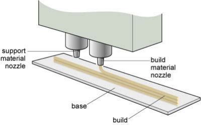
FDM cannot handle overhanging structures with much success. Therefore, systems are often equipped with a second extrusion head for depositing 'sacrificial' material. This is commonly dissolved in a solvent that does not affect the properties of the build material.
Manufacture:
FDM is essentially a rapid prototyping technique that with careful control can be used to create functional parts. Consideration needs to be given to the following:
- Molten or semi-molten material is exposed to oxidising atmosphere (i.e. air). An inert atmosphere such as nitrogen or argon can be used to reduce oxidation and improve layer-to-layer adhesion.
- Unsupported material can be supported by sacrificial structures.
Materials:
Limited to thermoplastics. Common examples include:
- polycarbonates (some grades can be sterilised and used for implantation applications)
- ABS (available in many solid and translucent colours)
- polyphenylsulfone (selected for high-strength applications)
- PETG (impact resistant, but higher density than ABS).
Design:
Component design is limited by the following:
- Strength and thoroughness can be influenced by many factors including time of build, atmosphere and even polymer colour.
- Overhanging regions need extra designing.
- Structures requiring more than a single filament width require care to ensure voids are not created between filaments.
- Support structures can only be placed where they can be removed (i.e. not inside internal voids like those required to create a ball).
See Also: Direct metal deposition (DMD), 3D printing, Selective laser melting (SLM)
This article is a part of Manupedia, a collection of information about some of the processes used to convert materials into useful objects.
Rate and Review
Rate this article
Review this article
Log into OpenLearn to leave reviews and join in the conversation.
Article reviews