
Three main concepts
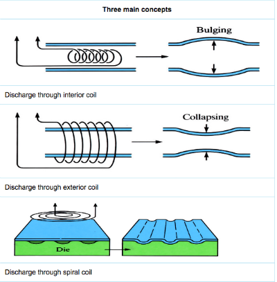
Bulging or expansion ring
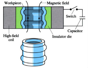
The Magneform process uses the principle of electromagnetic metal forming, in that a controllable force is exerted on a current-carrying conductor (metal workpiece) when placed in a certain direction in an electromagnetic field. This is the same principle as is used in the electric motor. The basic circuit has a switch that produces a damped sinusoidal discharge current when closed. A capacitor voltage in the order of 8 kV is used and the discharge current (Imax) is 100–400 kA. The forming time is approximately 100 µs. The discharge current produces an electromagnetic field in the coil. If an electrically conductive workpiece such as an aluminium tube is inserted into the coil, then a pressure pulse can deform the metal.
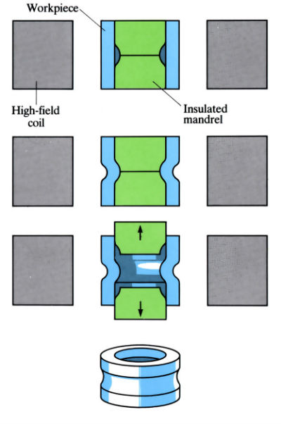
Stages in tube shrinking
Manufacture:
- In electromagnetic forming, the electrical energy from a capacitor bank is passed through a coil. A large magnetic field builds up around the coil, inducing a voltage in the workpiece. The resultant high current builds up its own magnetic field. These two magnetic fields of force are opposite in direction and repel each other, causing deformation of the workpiece.
- If the coil is placed on the inside of a tubular workpiece, the magnetic force (pressure up to 340 MN-2) moves the workpiece at velocities up to 300 ms-1 and causes the tube to bulge and assume the shape of the die cavity. Actual forming time 50–100 µs.
- If the coil is placed around the outside of the workpiece, then parts may be shrunk onto formed mandrels.
- Field-shaped coils may be used to concentrate the magnetic field of force when irregular shapes are to be formed.
- The strength of the magnetic force can be closely controlled, allowing metal to form over plastic, glass and composites.
- Repetitive machines can be used at up to 40 parts per minute.
- Magneform machines make no physical contact, so no lubrication is required. There is no tool wear or maintenance.
- Process is primarily used for swaging or expanding tubular shapes. It may also be used for embossing, punching, forming and shrinking operations.
Materials:
- Magneform works best on materials with a high electrical conductivity, such as aluminium, copper, brass and low carbon steel.
- The resistivity of material is best if it is less than 15 x 10-6 Ω cm.
- Materials of poor conductivity, such as stainless steels, can be formed by using a highly conductive driver, such as aluminium sheet, or a specially built high frequency machine.
- Different materials can be assembled together, such as metal rings on to plastic, glass, composites and rubber.
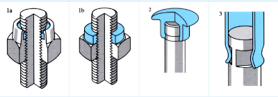
Design:
- a. Conventional nut and locking washer
b. Magnetic pulse assembly method - Knob or handle magnetically swaged onto ground grooves in hardened shaft.
- Tube attachment magnetically swaged onto ground flats of hardened shafting for torque transmission.
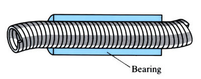
- Bearing surfaces can be magnetically swaged onto non-bearing surfaces.
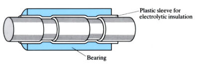
- Bearing material magnetically swaged onto drive shaft of non-bearing material.
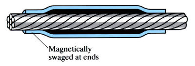
- Stabilising bearings magnetically swaged to flexible drive shaft.
See Also: Fasteners, Injected metal assembly, Manual metal arc welding, Adhesive bonding, Soldering and Brazing.
This article is a part of Manupedia, a collection of information about some of the processes used to convert materials into useful objects.
Rate and Review
Rate this article
Review this article
Log into OpenLearn to leave reviews and join in the conversation.
Article reviews