
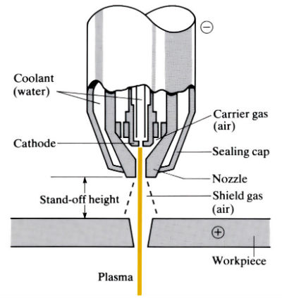
Air plasma torch construction
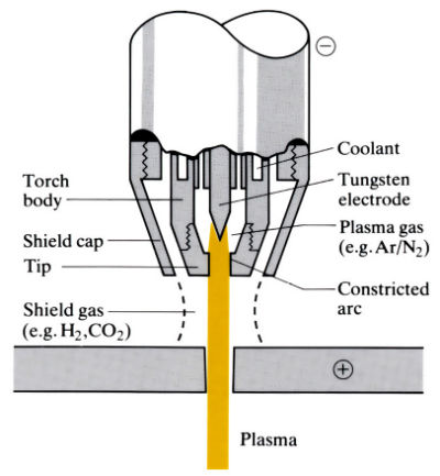
Dual gas plasma torch construction
Water injection plasma torch construction
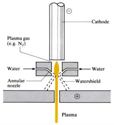
Material removed by a high-velocity stream of “plasma” produced in water-cooled nozzles by electrically ionising suitable gases such as argon, hydrogen, nitrogen, carbon dioxide, air, or mixtures of these gases. “Plasma” consists of a mixture of neutral atoms, free electrons and positive ions. The plasma arc, which can reach temperatures of up to 28,000°C, is transferred to the workpiece, which is usually positive, where it “blows away” the molten metal. Energies of approximately 10kWh m-3 and thermal efficiencies of 85–90% can be achieved. There are three commonly used plasma systems.
Manufacture
- An alternative to flame cutting, laser cutting, electrical discharge wire cutting and abrasive jet cutting.
- Used mainly for profile cutting of metal sheets and slabs up to 200 mm thick, but can also be used for cutting, turning, grooving and piercing holes and slots.
- “Stand-off” height critical, hence process is often combined with other operations in CNC “fabrication centres”.
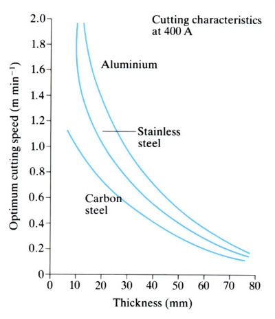
- Production parameters vary with material, workpiece thickness and system. Typical values are shown in the table below.
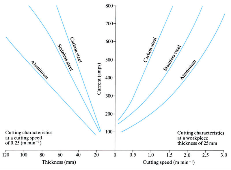
| Parameter | Process | ||
| Dual gas | Water | Air | |
| Comparative cost for 16 mm thick mild steel sheet | 7.4 | 10 | 7.1 |
| Cutting speed for 16 mm mild steel sheet (m min-1) | 1.9 | 2.1 | 1.9 |
| Power consumption for 16 mm mild steel sheet (kW) | 15 | 89 | 64 |
| Current for 16 mm mild steel sheet (A) | 150 | 400 | 250 |
Materials:
- Almost any conducting material can be cut. Materials currently cut include brass, bronze, nickel, tungsten, aluminium, mild steel, carbon steel, stainless steel, copper, cast iron, molybdenum, monel, inconel, magnesium and titanium.
- A heat-affected zone of up to 5 mm can occur depending on material, thickness and cutting speed.
- In some materials gas pick-up may occur from the plasma and/or shielding gas, e.g. hydrogen pick-up in steel.
Design:
- Although thicknesses from 0.75 to 200 mm can be cut, the usual range is 5–25mm.
- Side of cut usually has a taper of 2–7°, but by careful control of production parameters this can be reduced to 1–2°.
- Surface finish is usually in the range Ra = 1.6–3.2 µm but values Ra = 0.8 µm can be achieved.
- Smooth, burr-free cuts, free from contamination are produced although “dross” firmly attached to the underside of the cut can sometimes be a problem.
- Positional tolerances for hole and slot piercing range from ±0.8 mm on sheets 5–35 mm thick, to ±3 mm on slabs 150–200 mm thick.
- Diameter tolerances are ±0.25 mm for 5 mm diameter holes, and ±0.50 mm for 10 mm diameter holes in 4 mm thick steel sheet.
- Minimum hole size for hole piercing is about 3 mm.
- Minimum corner radius of 4 mm on thin sheets, which increases with cutting speed to 40 mm at cutting speeds of 6 m min-1.
See Also: Flame cutting, Laser cutting, Abrasive jet cutting and Electrical discharge wire cutting.
This article is a part of Manupedia, a collection of information about some of the processes used to convert materials into useful objects.
Rate and Review
Rate this article
Review this article
Log into OpenLearn to leave reviews and join in the conversation.
Article reviews