
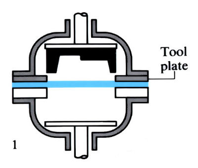
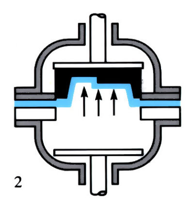
Female forming:
- Blank coated with graphite-releasing agent, preheated in separate furnace. Transferred to double-domed hydraulic press, with built-in die heaters in the domes.
- Air pressure applied to expand sheet into close contact with die.
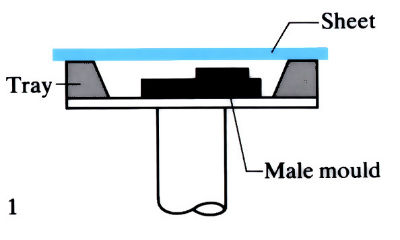
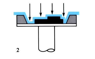
Female drape forming:
- Blank coated with releasing agent, clamped over tray containing male mould and heated to correct temperature.
- Air pressure applied forcing metal into close contact with the mould.
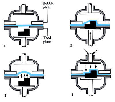
Plug-assisted snap back male forming:
- Blank coated with graphite and preheated in separate furnace. Transferred to domed press.
- Blank preformed into bubble.
- Male forming tool pressed into bubble to remove “wrinkles” from preformed sheet.
- Air pressure applied forcing metal into close contact with the die.
Manufacture:
- An alternative to deep drawing, die casting and rubber die pressing for metals, and to injection moulding and vacuum forming for polymers.
- “Female forming” is used for small components of simple design.
- “Female drape forming” is used for larger, shallow components, but at increased cost due to higher tool and material costs.
- “Male forming” is used for deeper, more complex components, giving optimum metal distribution and wall thicknesses, but at higher cost.
- Tooling costs are low since only one cast die is required.
- Low to medium production numbers due to high material costs and slow cycle times.
- Economic production range extended as complexity of component increases.
- Cycle times, which depend on material and component size and complexity, are 5–40 min.
- Increasing the strain rate to reduce cycle times may cause cavitation in the material. This can be eliminated by HIPing, but at considerable expense (see J04).
- Low flow stresses allow cast aluminium tooling except for deep drawn parts formed at higher superplastic temperatures, which require nodular cast iron.
- Ideal for prototype work since tooling is easily modified.
- Male forming allows multiple parts to be formed in one cycle, but this technique needs careful design and control of production parameters.
- Re-entrant parts produced using split tooling and sliding surfaces, but with increase in die cost and cycle times.
- Pressures depend on material and component size and geometry: 350–1500 kPa is typical for aluminium alloys using special presses.
- Has been successfully combined with diffusion bonding with titanium (using argon instead of air), but not with aluminium alloys due to the adherent oxide layer.
- Typical products include seat frames, luggage racks and seat backs for trains, camera housings, door and body panels for the automotive industry, covers for undercarriage gear, and decorative panelling.
Materials:
- Almost all alloys become superplastic with the correct combination of grain size, strain rate sensitivity (m value) and temperature. These parameters vary widely with material, but maximum m values of 0.5–0.9 and grain sizes of 1–2 µm are typical.
- Only alloys based on aluminium, nickel, stainless steel, titanium and zinc are available commercially, and of these the most commonly used are aluminium, titanium and stainless steel (e.g. Supral 100 (Al—6Cu—0.4Zr): temperature range 450–500˚C, m value 0.5; titanium 318: temperature range 850–950˚C, m value 0.7–0.9).
- Alloys are being developed that are superplastic at high strain rates, with a view to increasing cycle times, but this often results in 1–2% microcavities, which impair the mechanical properties.
- Al/Li/Cu/Mg alloys are being developed for use in the aerospace industry, due to their high strength/weight ratio, but at present they require low strain rates and hence long cycle times.
- Unlike other Al alloys, Supral 5000 can be decoratively colour anodised and is suitable for marine or extreme industrial environments.
- The small grain size leads to poor creep properties, and for creep resistant applications a grain coarsening heat treatment may be necessary, as in the Gatorising process applied to superplastic nickel alloys.
Design:
- Aspect ratio limited to avoid excess thinning, depth ≤ 0.15 x perimeter.
- Allowances must be made for different thermal expansions if die and component are of different materials.
- Sharp corners result in excessive thinning with risk of fracture during production or use, and may also cause wrinkling in the component. Minimum section radius = 5 x local gauge thickness (obtained by assuming constant volume and uniform thinning).
- Re-entrant angles are possible, but increase production costs.
- A small draft angle is usually necessary for stripping component from the die (3˚ minimum).
- Surface finish depends on sheet material and die condition, but is typically 0.8–3.2 μm Ra.
- More detail can be incorporated into the design than by pressing, deep drawing or rubber die pressing.
- Component sizes typically 900 mm x 600 mm.
See Also: Deep drawing, Fluid and rubber die forming, Die casting, Injection moulding and Vacuum forming.
This article is a part of Manupedia, a collection of information about some of the processes used to convert materials into useful objects.
Rate and Review
Rate this article
Review this article
Log into OpenLearn to leave reviews and join in the conversation.
Article reviews