

4.2 Basic principles of wireless transmission
I've never quite lost the sense of wonder at the way information can be transmitted with no visible link between the sender and recipient. When I was a child I used to think that sound came through the wire linking my family's radio to the mains electricity supply (I was born before the days of battery-powered transistor radios) and I couldn't understand why my parents referred to it as 'the wireless' – since clearly it wasn't. I now know that the wire simply fed the radio with the electrical power it needed. The radio signals were picked up by a special electrical conductor called an antenna. (Another name for antenna is aerial and you are likely to see these terms used interchangeably, both within this course and elsewhere.)
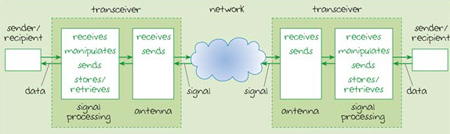
Radio signals arrive through the air as fluctuations in the electromagnetic field of a radio wave. This induces a fluctuating electrical current to flow in the antenna. These fluctuations are detected and translated into data. But an antenna can be used in two different ways. Fluctuations in electrical current flowing in an antenna can also emit a radio signal, so an antenna can be used to both receive and send radio signals. Most devices operating in radio networks are transceivers (that is, they can both send and receive radio signals) and will use the same antenna when sending and receiving. Figure 8 (Section 2) can be developed to represent a wireless network. This is shown in Figure 11 where we have broken down the components within the radio transceiver to show the antenna and the signal processing components.
When signals are travelling in cables, they follow the path of the cable, even though this may twist and turn. For this reason, cables are described as 'guided' media. Radio signals are not guided in this way. The electromagnetic waves carrying the signal can propagate in all directions, and may spread out in a spherical pattern as shown in Figure 12.
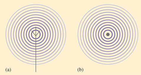
The term 'wavefront' refers to all points on a wave that are equidistant from its source. In this case, the wavefronts are represented by the concentric circles in both figures. Notice how the circles become fainter with distance from the centre, representing the way the signal weakens. Figure 12(a) shows a representation of a side view of an antenna. In practice antennas come in many shapes and sizes, but this representation is often used in diagrams regardless of the actual design of the antenna. In Figure 12(b) we have shown a representation looking down onto the antenna.
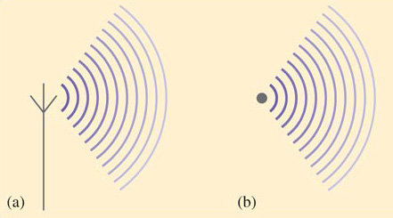
Antennas can be designed to be directional so that the signal power is directed into a beam (Figure 13). This allows the signal to travel further for the same power. However, in general, the attenuation of a radio signal is greater than the attenuation of a signal travelling an equivalent distance via a cable.
The maximum practical distance that a signal can be propagated is influenced by factors such as the signal frequency and strength, the physical environment and the design of the antenna. Low-frequency waves can travel further than high-frequency waves. Low-frequency waves are also more efficient at penetrating physical barriers such as walls and floors – something that high-frequency waves, like visible light, can't do. So it is the waves at the lower frequency end of the electromagnetic spectrum that are used for over-the-air communications. These include the radio and microwave frequencies.
Activity 16: self-assessment
Refer back to Figure 6 in Section 2. Approximately what section of the electromagnetic spectrum is occupied by radio waves? (That is, at approximately what frequency do they start and at approximately what frequency do they finish?)
Answer
Radio waves occupy the portion of the electromagnetic spectrum lying between about 103 Hz (1 kHz) and 1010 Hz (10 GHz).
From the answer to Activity 16, we can calculate the approximate frequency range of radio waves. This is the difference between the highest and lowest frequencies in that section which, in this case, is somewhere around 1010 Hz minus 103 Hz (10 000 000 000 Hz minus 1 000 Hz). If we were to calculate an answer from these figures the result would be 9 999 999 000 Hz or approximately 1010 Hz.
You may have been surprised to find that the result of deducting 1 000 Hz (1 kHz) from 10 000 000 000 Hz (10 GHz) gave an approximate result of 10 000 000 000 (10 GHz). After all, we have taken something away from the original 10 GHz, so how can the answer be approximately the same as the figure we started with? This is because 10 GHz is extremely large compared to 1 kHz – in fact 10 million (107) times greater. So subtracting 1 kHz is insignificant.