1.7 Quadrature amplitude modulation (QAM)
It is possible to combine ASK, FSK and PSK. One benefit of combining different modulation methods is to increase the number of symbols available. Increasing the number of available symbols is a standard way to increase the bit rate, because increasing the number of symbols increases the number of bits per symbol. It is rare for all three methods to be combined, but very common for ASK and PSK to be combined to create Quadrature amplitude modulation (QAM).
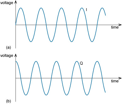
QAM is based on the application of ASK and PSK to two sinusoidal waves of the same frequency but with a phase difference of 90°. Sinusoidal waves 90° apart are said to be in a quadrature phase relationship. It is customary to refer to one of these waves as the I wave, or in-phase wave or component, and the other as the Q wave, or quadrature wave or component (Figure 1.7).
You may recognise the I wave in Figure 1.7 as a sine function and the Q wave as a cosine function. These functions are said to be orthogonal to each other. If two signals are orthogonal, when they are transmitted simultaneously one can be completely recovered at the receiver without any interference from the other.
The I and Q waves remain orthogonal if either or both of them are inverted (multiplied by –1, or flipped vertically). Negative amplitudes just mean that the wave is inverted.
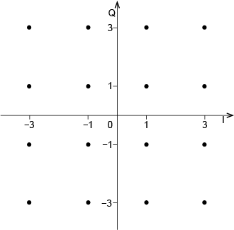
The set of symbols in QAM can be conveniently represented on a signal constellation diagram (Figure 1.8). This is a plot of the I and Q amplitudes with I on the horizontal axis and Q on the vertical axis. Each dot in Figure 1.8 is a symbol, as it represents a unique combination of amplitude and phase of the I and Q waves. So, in each symbol period, only one of the ‘dots’ is transmitted. As there are 16 symbols, this version of QAM is called 16-QAM.
To understand what each dot in the diagram represents, take the top left one. This represents a symbol where the Q wave is at an amplitude of 3 and the I wave is at an amplitude of –3. The minus sign means the I wave is inverted (or phase shifted by 180°) relative to the I wave in Figure 1.7(a).
As the number of symbols increases, more data bits are transmitted per symbol. For example, 64-QAM is a QAM scheme with 64 symbols, and 256-QAM is a scheme with 256 symbols. 256-QAM conveys 8 bits per symbol (as 256 = 28), so achieving twice the data rate of 16-QAM for the same symbol rate.
Activity 1.7 Self assessment
How many bits are represented by each symbol in 64-QAM? Sketch a constellation diagram for 64-QAM.
Answer
For 64-QAM, the number of symbols M = 64. There are six bits per symbol, asM = 2n and 64 = 26.
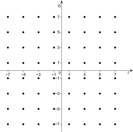
A constellation diagram for 64-QAM might look like this:

The points on the diagram in the answer to Activity 1.7 are placed at values of +/−1, 3, 5 and 7. The actual amplitudes used in practice are likely to be different; but if the spacing between constellation points remains the same (2 in this case) and we keep adding more points in this way, then we are increasing the power in the signal. The further away from the origin a constellation point is, the more power is required in the signal. Alternatively, it could be necessary to keep the maximum signal power constant whether we are using 16-QAM or 64-QAM, for instance. This would mean packing the points closer together in 64-QAM than in 16-QAM. However, if the points are closer together then adjacent symbols will be more likely to be misinterpreted at the receiver as a neighbouring symbol. One of the effects of noise (which is unavoidable in communication) is to add a degree of uncertainty about which symbol has arrived at the receiver.


