
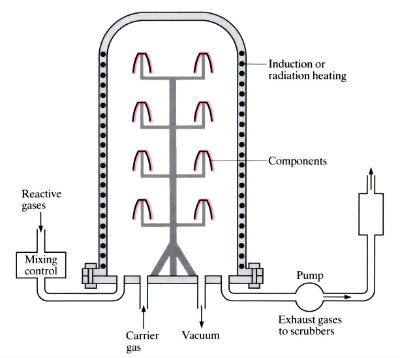
Cold wall system

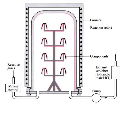
Hot wall system
Manufacture:
- A “high” temperature process. Cheaper, more suitable for mass-production than PVD (Physical vapour deposition), needing no special attachments, clamping or rotation.
- A batch process. Throughput depends on component size and coating thickness (greater than PVD).
- Coating rates vary greatly from 1 μm h-1 for Ti (C, N) coatings to 500 μm h-1 for tungsten, typically 5–20 μm h-1.
- Coating of machine and press tools at a higher temperature (>900°C) than PVD (>500°C) means that subsequent heat treatment is necessary to restore the hardness of tool steels. This can lead to cracking and distortion, so for close-tolerance tools PVD is preferable. However, CVD is suitable for cemented carbide inserts as the higher temperatures do not usually affect their properties. These tips are produced at a rate of 2000–10,000 min–1. CVD on cold forming and punching tools reduces tool loads and increases lives by up to 40x.
- There are several varieties of the basic CVD process, including moderate temperature CVD (MT-CVD), plasma arc CVD (PACVD) and diffusion CVD. MT-CVD uses organic nitriles as a source of carbon and nitrogen (instead of CH4 and N2), and the lower temperatures reduce the risk of edge brittleness in cemented carbide tips. PACVD uses an argon plasma to heat the substrate material, thus lowering the temperature of the process to 400–500˚C. In diffusion CVD the coating, substrate and temperature are chosen so the coating reacts with the substrate to produce an alloy or intermediate compound.
- “Hot-wall” chambers are externally heated, and a certain amount of plating of the chamber wall occurs. Only the workpieces are heated in a “cold-wall” chamber, usually by induction, so no redundant plating occurs.
Materials:
- CVD coatings usually have better adhesion than PVD, due to the higher temperatures. They are of near theoretical density, giving rise to good oxidation resistance, and are often used to “infill” more porous coatings.
- Grain size of coatings varies from 0.01 to 10 μm.
- Coatings must be deposited on a hard substrate (55–60 Rc) materials.
- Unlike PVD, multi-layer coatings can be deposited.
- One of the major applications of CVD is to produce wear resistant coatings on machine and forming tools. Nitrides, carbides, oxides and borides have all been used for this purpose, but the most common materials are TiN (characteristic golden colour), TiC or TiN/TiC combinations.
- TiC is harder than TiN (3200 Hv /2500 Hv). TiN has a greater oxidation resistance, and the coefficient of thermal expansion is greater than that of TiC and closer to that of high speed steels, leading to a more stable coating. Optimum properties are obtained by using alternative layers of TiC and TiN, or a Ti (C, N) coating.
- TiC coatings on cemented carbide inserts can cause decarburisation, leading to edge brittleness and premature failure. This can be overcome by using MT-CVD.
- The use of TiC/TiN coatings on machine tools gives a significant improvement in tool life. Improvements of 10x are common, and in some cases improvements of 200x have been reported.
| Coating material | Plating vapour | Temperature (°C) |
| Graphite | CH4/H2 | 2200–2400 |
| BCl3/NH3 | 1750–1950 | |
| Boron nitride | BF3/NH3 | 1750–1950 |
| SiF4/H2/NH3 | 1200–1400 | |
| Silicon nitride | SiCl4/H2/NH3 | 1200–1400 |
| Aluminium oxide | AlCl3/H2/CO2 | 1200–1400 |
| Tungsten | WCl6/H2 | 900–1100 |
| Titanium nitride | TiCl4/Ti/H2/N2 | 800–1000 |
| Titanium carbide | TiCl4/Ti/H2/CH4 | 600–1000 |
| Tungsten carbide | WF6/H2/C6H6 | 400–550 |
Design:
- Complex shapes, including narrow internal surfaces such as extrusion dies for aluminium window frames, can be evenly coated.
- Surface finish depends on original surface of component, but for TiC/TiN coatings is in the range 5–40 μm with 7–8 μm being typical. Surface finish is matt and can be greatly improved by starting with a good surface and giving a light polish after heat treatment.
- Coating of complex shapes – such as twist drills, and dies greater than 600 mm in diameter – is not usually possible due to distortion.
- Component size depends on size of the reaction chamber, which can exceed 1 m diameter by 2 m long.
- Has been used to coat a wide variety of components from pen nibs to the rocket nozzles at the rear of the space shuttle, but is usually used for cutting and forming tools such as compaction dies for ceramics, air bearing shafts (W2C at 500°C) and aluminium extrusion dies (W2C).
- Free standing shapes, such as crucibles, tubes and plates, can be produced by coating suitable formers which are later removed.
See also: Toyota diffusion (TD), Thermal spraying, Electroplating, Electroless plating, Ion implantation and Plasma nitriding/caburising.
This article is a part of Manupedia, a collection of information about some of the processes used to convert materials into useful objects.
Rate and Review
Rate this article
Review this article
Log into OpenLearn to leave reviews and join in the conversation.
Article reviews