2.3 Attenuation
Activity 2
At approximately what wavelength is the attenuation of optical fibre lowest? What, approximately, is the attenuation at that wavelength? What other wavelengths are used and why?
Answer
The attenuation of fibre is lowest in the wavelength range 1500 to 1600 nm, where it is typically around 0.2 dB km−1. This is known as the ‘1500 nm window’, or more accurately the ‘1550 nm window’. Wavelengths around 1300 nm are widely used, however, because the dispersion of standard single-mode fibre is lower around 1300 nm and because optical devices are easier to manufacture at that wavelength (and are therefore cheaper). The attenuation in the 1300 nm region is still very low, being less than 0.5 dB km −1.
Wavelengths around 850 nm are also used because devices are even cheaper at that wavelength. For short distances (such as in LANs) the higher attenuation at 850 nm is still acceptable.
In order to determine the distance achievable with a given system, a link power budget is calculated. I shall illustrate this with examples based on Gigabit Ethernet standards. The material that follows refers to the IEEE 802.3 standard, 2002 edition.
The Gigabit Ethernet standards describe the use of fibre in all three categories identified in the last section. Two different versions of 50/125 μm multimode fibres are specified, differing in their bandwidth. Here I am talking about the version with a bandwidth specified by the ‘bandwidth-distance product’ of 400 MHz-km. (The meaning of the bandwidth-distance product is explained later.)
The 1000BASE-SX standard (‘S’ for ‘short wavelength’) specifies operation over either 50/125 μm or 65/125 μm multimode fibres using an optical wavelength of 850 nm. Consider first operating over 50/125 μm multimode fibre and the parameters of Table 1, which have been selected from the IEEE 802.3 standard.
| Parameter | Value |
|---|---|
| Minimum launch power | −9.5 dBm |
| Receive sensitivity | −17 dBm |
| Allowance for connector and splice losses | 1.5 dB |
| Maximum fibre attenuation | 3.5 dB km−1 |
| Link power penalties | 4.1 dB |
The minimum launch power and the receive sensitivity (the minimum power level required at the receiver) are requirements for the terminal equipment. The value for the maximum fibre attenuation is a requirement of the fibre used in the link, while the allowance for connector and splice losses and the ‘link power penalties’ are additional losses that need to be included. Several factors contribute to link power penalties, defined in paragraph 1.4.157 of IEEE 802.3 as follows:
1.4.157 link penalties: For fiber optic links, the power penalties of a link not attributed to link attenuation.
These power penalties include modal noise, relative intensity noise (RIN), intersymbol interference (ISI), mode partition noise, extinction ratio, and eye-opening penalties.
You do not need to know the details of these power penalties, but in general terms modal noise, RIN and mode partition noise are all effects due to features of the light source (in some cases also of the fibre). ‘Eye opening’ is to do with the tolerance to noise and jitter at the receiver, the concept of the data ‘eye’ coming from the appearance of the received signal when inspected with an oscilloscope.
With this information we first note that between the transmitter and receiver the maximum loss can be:

Notice that the difference between the two powers in dBm is in decibels, dB, not dBm, as it is a power ratio rather than an absolute power.
From this 7.5 dB we subtract the 1.5 dB allocated to the connectors and splices (splices are permanent joints between fibres, discussed further in Section 2.6) and 4.1 dB power penalties, leaving 1.9 dB for the fibre attenuation. This allows a length of 1.9/3.5=0.54 km (540 m). For this type of fibre the standard specifies an operating distance of up to 500 metres.
SAQ 4
Another of the Gigabit Ethernet standards, 1000BASE-LX, is specified for use with ‘long’ wavelengths (the ‘1300 nm window’) and can be used with single-mode as well as multimode fibre (50 μm and 62.5 μm). Using the data in Tables 2 and 3, draw up power budgets to determine the maximum range for 1000BASE-LX systems over:
(a) 50 μm multimode fibre
(b) 10 μm single-mode fibre.
Answer
(a) For the 50 μm system, the maximum loss between the transmitter and receiver can be:

1.5 dB of this available power budget is used by the connectors and splices and 5.0 dB for link power penalties, leaving 1.0 dB for the fibre attenuation. This allows a length of not more than 1.0/1.5 = 0.67 km, or 670 m. The standard specifies an operating distance of up to 550 metres.
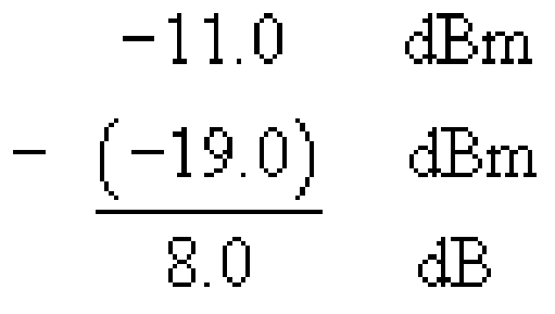
(b) For the 10 μm single-mode system, the maximum loss between the transmitter and receiver can be:

1.5 dB of this available power budget is used by the connectors and splices and 3.3 dB for link power penalties, leaving 3.2 dB for the fibre attenuation. This allows a length of 3.2/0.5 = 6.4 km. The standard specifies an operating distance of up to 5 km.
| Parameter | Value |
|---|---|
| Minimum launch power | −11.5 dBm |
| Receive sensitivity | −19 dBm |
| Allowance for connector and splice losses | 1.5 dB |
| Maximum fibre attenuation | l.5 dB km1 |
| Link power penalties | 5.0 dB |
| Parameter | Value |
|---|---|
| Minimum launch power | −11 dBm |
| Receive sensitivity | −19 dBm |
| Allowance for connector and splice losses | 1.5 dB |
| Maximum fibre attenuation | 0.5 dB km1 |
| Link power penalties | 3.3 dB |
When referring to the wavelength of light in the context of optical-fibre communications it is the convention to refer to the wavelength that the light has in free-space.
