

3.3 Model produced by computer-aided design
A CAD model is converted into a digital representation so that each layer can be defined for input into the AM apparatus.
It would be feasible to define each layer to be manufactured as a series of polygons, essentially a separate CAD model for each layer. However, AM equipment has the function to vary the layer thickness, which affects the build rate and finish quality.
The key feature of the STL file format was that only a single CAD representation was required, which could be easily exported into a digital representation of the layers. To achieve this, data needs to define locations on the surface at any location. This is trivial for a simple shape such as a cube. It is more complex for a shape with a curved surface.
STL files simplify a complex shape into a 3D set of triangles, enabling a surface to be approximated. By knowing the location of a triangle it is possible to calculate the position of any of the edges of the triangle.
Figure 8 shows a cube surface divided into triangles. This can be done by using two triangles for each face, making a total of 12 triangles for six faces. The definition of the square face by the triangles is complete – there is no discrepancy between the model and reality.
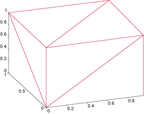
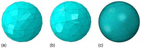
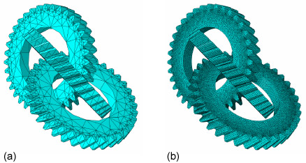
Figure 9 shows three versions of a sphere surface made of triangles. A sphere can never be perfectly defined by triangles, but the more triangles that are used, the closer the shape is to a true spherical surface – and the more data that is needed. Figure 10 shows a real component defined by triangles.
Now contemplate the complexity of the reconstructed jawbone shown in Figure 4. It isn’t hard to imagine that a high number of triangles need to be defined in order to approximate its shape. If one line of computer code defines a corner of one triangle, it isn’t difficult to imagine that creating an STL file for a complex shape can be computationally intensive.
The advent of computers capable of creating STL files complex enough to define engineering components is one of the factors aiding the uptake of AM techniques.