
Induction hardening
Flame hardening
Manufacture:
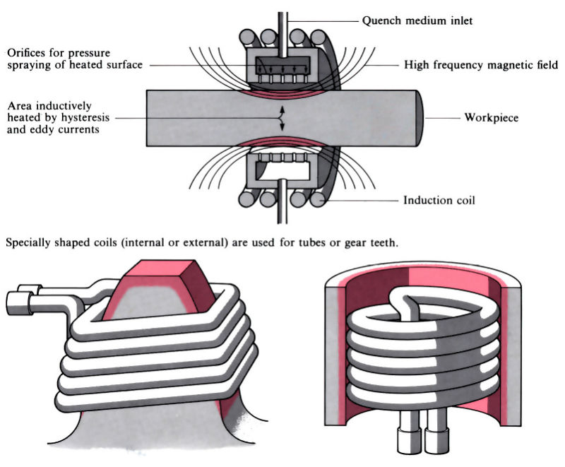
Induction hardening
- Surface of component heated by high frequency induction, the frequency and power requirements depending on size and geometry of component and depth of hardening required.
- Three main types of induction machines:
vacuum tube oscillator > 500 kHz
spark gap oscillator 10–30 kHz
motor generator 5–10 kHz - Heat-up times can be controlled to within ±0.1 s and should be less than 20 s to prevent distortion and avoid post-treatment machining or grinding.
- Process can also be used for through hardening of small components.
- Tempering and/or stress relieving can also be done by induction heating, often with the same induction coil.
- Process is easily automated and can give uniform quality and repeatability, although high capital and running costs make it most suitable for long production runs.
- Typical applications include gears, crankshafts and camshafts.
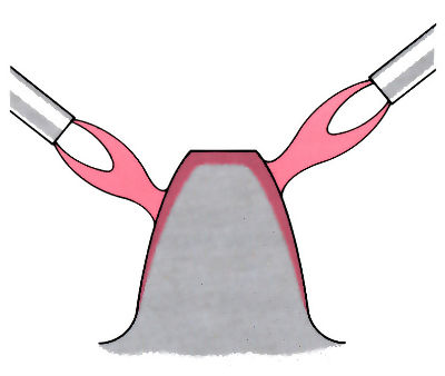
Flame hardening
- Heating by means of oxy-fuel burners.
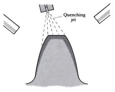
- Quenching jets follow burners, the quench rate being controlled by the distance from the jets to the burners and the volume of quenchant.
- Tempering and/or stress relieving flame often follows the quenching jets.
- Can be used on flat, circular or irregular-shaped components, but is best suited to circular components which can be rotated between centres.
- The steep thermal gradients required necessitate high flame temperatures, with the risk of overheating, burning and distortion, so the process is usually automated using specially shaped burners.
- Typical applications include gear teeth, brake drums, axles, cams and crankshafts.
Materials:
- Ferrous metals whose composition is such that the required hardness will be obtained on quenching from the austenite region: a minimum of 0.3% C. Most materials have at least 0.4% C, and up to 0.7% C.
- Plain carbon steels, alloy steels and grey, nodular and malleable cast irons; the temperature depends on the material:
750–760° C 0.5% plain carbon
900–800° C chromium–molybdenum alloy steels
950–980°C nodular iron - Alloy steels, although more expensive, produce greater case depths.
- The higher the carbon content, the greater the risk of cracks and/or distortion.
- Flame hardening is not usually suitable for steels with core strengths of greater than 900 MPa.
- Required core strength must be obtained by appropriate heat treatment before hardening.
- To enable carbides to go into solution during the short heating times, the carbides should be small, hence normalised structures are preferred.
- Fine grains give better control over the case depth and less chance of cracking and/or distortion.
- Very little grain grown occurs, due to short heating times.
- Little or no decarburising or oxidation due to short heating times.
- Surface hardnesses depend on composition, temperature and quenchant, but are usually in the range 350–700 Hv.
Design:
- Processes are best for cylindrical parts such as crankshafts, gears, axles and brake drums.
- Large gears can be treated one tooth at a time, and hardness pattern depends on method employed.
- Long thin components may require pre-heating.
- Flame hardening can be done on small selective areas.
- Case depths vary from 0.1 to 10 mm, depending on requirements. Induction hardening is used for small case depths which require smaller tolerances.
See Also: Ion implantation, Nitrotec process, Carbonitriding/carburising, Plasma nitriding/carburising, Chemical vapour deposition (CVD), Physical vapour deposition (PVD), Electroless plating, Electroplating and Toyota diffusion (TD).
This article is a part of Manupedia, a collection of information about some of the processes used to convert materials into useful objects.
Rate and Review
Rate this article
Review this article
Log into OpenLearn to leave reviews and join in the conversation.
Article reviews