
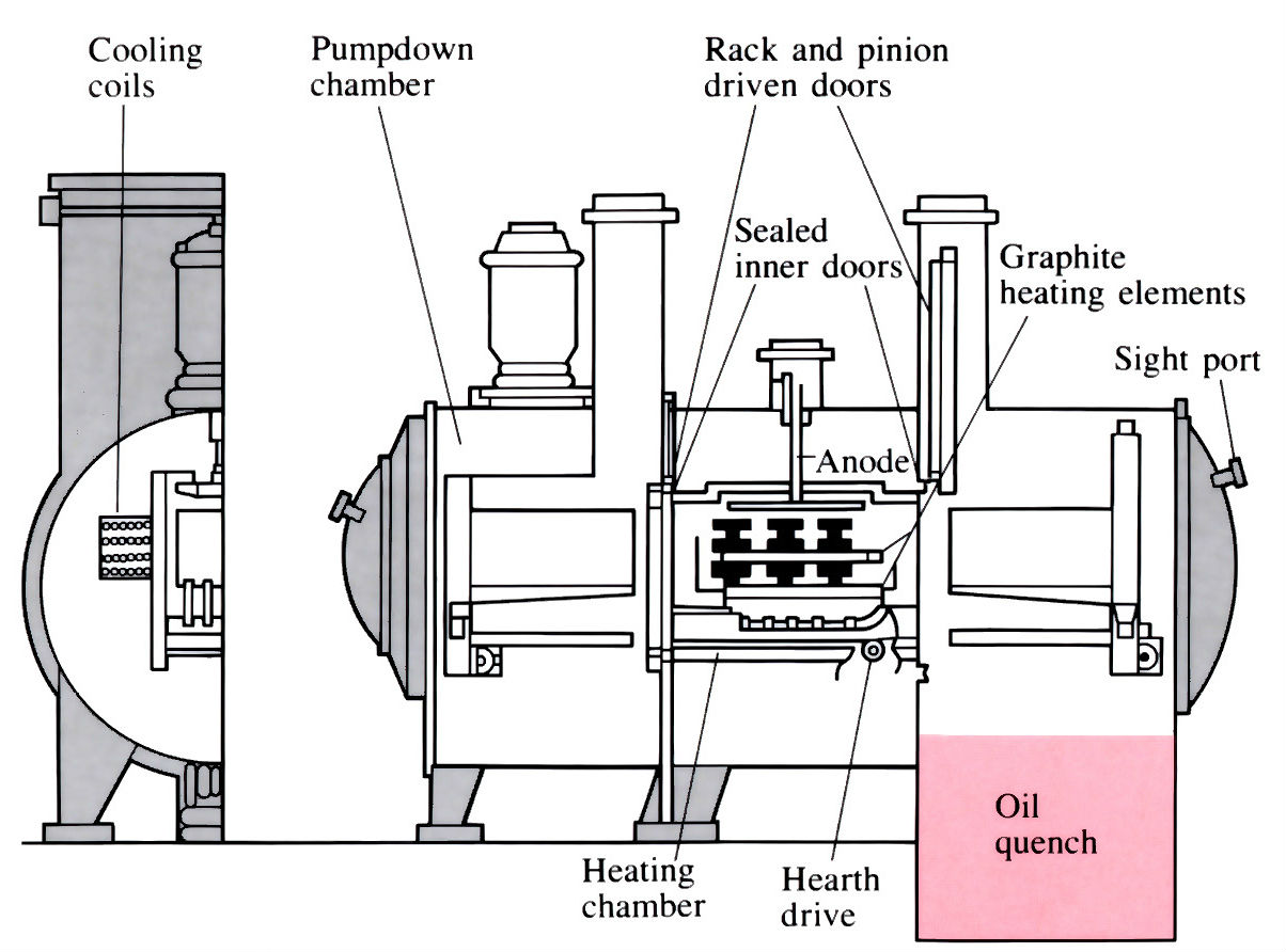
Plasma carburising furnace
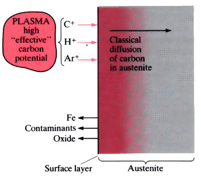
Plasma carburising
- Preliminary clean and degrease.
- Load components into basket and place in furnace.
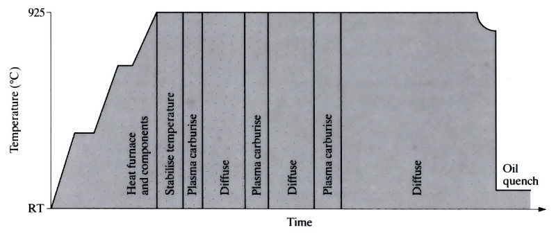
- Evacuate and heat.
- Introduce carburising gas and strike up glow discharge. Hold until carburising is complete.
- Switch off gas and plasma, and hold under vacuum (diffusion period).
- Cool slightly (925–850°C) before transferring out of hot zone to be quenched in warm, stirred oil (80°C).
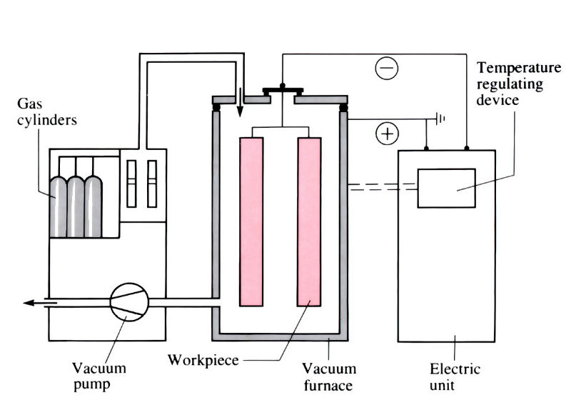
The basic elements of a plasma nitriding installation
Plasma nitriding
- Preliminary clean and degrease.
- Load into furnace.
- Evacuate and introduce gas.
- Strike up glow discharge and hold until nitriding complete.
- Switch off gas and glow discharge.
- Cool and remove from furnace.
Manufacture:
Plasma carburising
- Carried out in a batch-type vacuum furnace with integral quenching tank (oil).
- 360° radiant heating from graphite elements.
- Operating pressure 10-3–1.5 MPa.
- Work is held at a negative potential of 400–800 V with respect to the chamber.
- Operating temperatures up to 1050°C, but usually below 950°C.
- Carbon source is hydrocarbon gas (methane or propane), often diluted with nitrogen, hydrogen and argon, which is bled into the vacuum chamber at a few litres per minute.
- Very little exhaust gas results, hence no risk of pollution.
- Surface of component is cleaned by “sputtering” and hydrogen reduction of any oxides.
- “Sooting” – which occurs in low pressure gas carburising – is eliminated, since carbon is only present in the thin discharge layer which surrounds the workpiece.
- Capacity depends on furnace size, but is limited to 400 kg in the UK.
- High capital cost of equipment, so process is only suitable for long production runs or short runs of “specialised” components.
- Whole process is capable of automatic control and good repeatability.
Plasma nitriding
- Similar to plasma carburising, but no heating is required since the kinetic energy of the ions striking the workpiece produces sufficient heat. No quench tank necessary.
- Operating temperature lower than for conventional gas nitriding, usually less than 550°C.
- Furnaces of 5 tonnes capacity are available in the UK.
- Nitrogen is bled directly into the furnace which operates at 10–100 Pa.
Materials:
Plasma carburising
- Any steel which can be gas carburised should be capable of plasma carburising, which relies on the same principle – that of increasing the carbon content at the surface to produce a sufficiently deep and hard layer on quenching. Plain carbon steels, alloy steels and cast irons can be treated, but should have a carbon content below 0.4% (and preferably below 0.25%) to produce a tough core.
- Process sometimes produces an over-high carbon content in the case profile, therefore a repeated carburise-diffuse sequence is adopted, relative process times are shown below. This is also used for producing deep cases.
- The shorter carburising times lead to less grain growth and an improvement in fatigue resistance by 30% compared with gas carburising.
Plasma nitriding
- Process relies on the formation of hard nitrides in the surface, hence alloying elements must be present in the steel to form these. The most common alloying elements are Al, Ti, Cr, Mo, W and V, which form a combination of nitrides in the case. Since many of these alloying elements are present in tool steels, they are ideal for nitriding.
- The nitrides produce a very hard surface, up to 1500 HV, with good fatigue resistance due to compressive stresses. Unlike carburised layers, much of this hardness is retained at temperatures up to 500°C.
- Although carbon does not play a part in the hardening process, the carbon content is usually kept below 0.4% to provide sufficient core toughness.
- Plasma nitriding does not produce the hard "white layer" of mixed iron nitrides that is often found in gas nitriding, and frequently spalls during service.
- Typical composition would be as follows:
- C 0.2–0.3%
- Mn 0.4–0.6%
- Al 0.9–1.4%
- Cr 0.9–1.4%
- Mo 0.15–0.25%
Design:
- Both processes produce little distortion of components, and hence minimise the need for post-treatment machining or grinding. Due to the lower temperatures employed, plasma nitriding gives the least amounts of distortion and is most suitable for tools, dies and precision parts.
- Selected areas can be hardened by using “stopping-off” with copper plating, as for ordinary carburising and nitriding processes.
- Both processes can give thin uniform layers over the whole surface of complex-shaped components, even small, “blind” holes.
- Component size limited by chamber size. Components 3 m long by 2 m in diameter can be plasma carburised in the UK.
- Case depths vary from 0.2 to 2 mm, with good tolerances.
See Also: Physical vapour deposition (PVD), Chemical vapour deposition (CVD), Electroplating, Electroless plating, Toyota diffusion (TD), Thermal spraying, Plasma arc spraying, Carbonitriding/carburising, Induction/flame hardening, Ion implantation and Nitrotec process.
This article is a part of Manupedia, a collection of information about some of the processes used to convert materials into useful objects.
Rate and Review
Rate this article
Review this article
Log into OpenLearn to leave reviews and join in the conversation.
Article reviews