

3.2 Exercise: Cantilever beam
Problem description
The problem is a simple cantilever beam. We only give outline instructions for most of this problem. You are required to issue the correct commands, based on your previous experience and the given data.
At the end of this exercise you are asked to use your knowledge in beam theory to calculate the bending stresses and to verify the results of your finite element analysis.
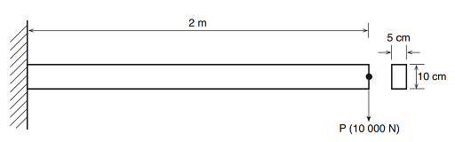
Figure 6 illustrates the problem and associated dimensions. Note that all dimensions should be converted to millimetres and appropriate units for the analysis. Recall that it is the user’s responsibility to insure that all units are consistent! The boundary conditions consist of fully fixing the node on the left.
The applied load is a single point load (force of 10000 N) applied to the right node of the beam. The relevant dimensions are as follows:
Length = 2 m
Depth = 10 cm
Width = 5 cm
The beam is made of steel with a Young’s modulus of 200 GPa and Poisson’s ratio of 0.30.
Origin
University of Alberta, MECE.
Interactive time required
45 to 60 minutes.
Features demonstrated
Linear analysis, Solid modelling, Meshing, Element table data, Post processing.
Summary of steps
- Set title and preferences
- Define element types and options
- Define material properties
- Define beam section parameters
- Create 2 Keypoints
- Create a line
- Set Global element edge size
- Mesh the line with a default mesh
- Apply displacement constraints
- Apply Force load
- Rotate axes
- Solve with default criteria
- Plot deformed shape
- List nodal displacement values
- List stresses in the beam
- Validate your results
- Exit the program.