
3.1 Gas boilers
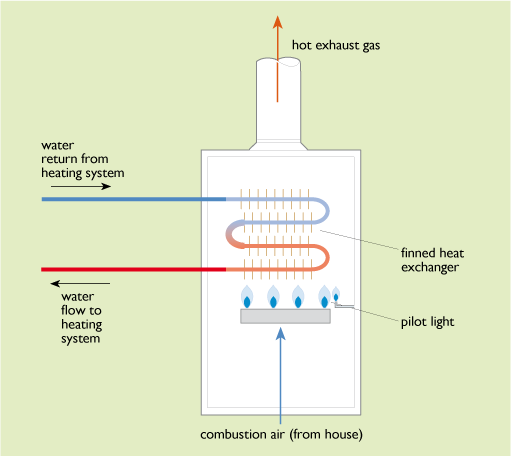
Figure 29 shows a simplified diagram of a typical 1980s domestic boiler. Combustion air enters at the bottom from the interior of the house to feed a large gas burner heating a set of finned heat exchangers. Water is pumped through these and circulated out to the heating system. The burnt gases exit at the top into a flue to the outside air. Such a boiler might have an output of 15 kW and an overall thermal efficiency of 65%.
More recent gas boiler designs have incorporated a number of improvements:
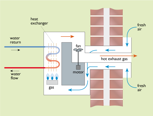
1 Balanced flues
Here the burner and heat exchanger are totally sealed off from the interior air of the building and the combustion air is blown through the boiler using an electric fan. Air is drawn in from the outside and the burnt gases are blown out again using a pair of concentric pipes via a single flue terminal on the outside of the building (Figure 30). Although this design does require a certain consumption of electricity, it allows the building to be made more airtight.
2 Electronic spark ignition
This has replaced the permanently burning pilot light used in many older boiler designs which could consume 10% of the total gas used.
3 Condensing gas boilers (see Figure 31)
The main component of natural gas is methane, CH4. When this burns it produces a large amount of water vapour:
- CH4 + 2 O2 → CO2 + 2 H2O
methane + oxygen → carbon dioxide + water vapour
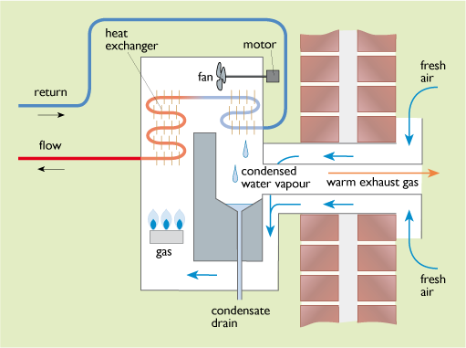
In a non-condensing boiler this water vapour is lost with the flue gases. In a condensing boiler the heat exchanger is made sufficiently large so that the return water from the heating system, which may be at about 50°C or lower, can cool the flue gas sufficiently to enable the water vapour to be condensed out recovering its latent heat of vaporization. The energy content of a fuel can be quoted as ‘higher’ or ‘lower’ values, depending on whether or not this latent heat of vaporization is recovered. The potential energy savings in using a condensing boiler depend on the difference between the gross and net calorific values for the fuel burned (also called the higher and lower heating values, HHV and LHV). Table 10 gives sample figures.
| Higher heating value/ MJ kg–1 |
Lower heating value/ MJ kg–1 |
Ratio | |
|---|---|---|---|
| Natural gas | 53.1 | 47.8 | 1.11 |
| Liquefied petroleum gas (LPG) | 49.2 | 46.0 | 1.07 |
| Light heating oil | 45.3 | 42.6 | 1.06 |
Where natural gas is the fuel, using a condensing boiler can increase the amount of heat extracted from the gas by up to 11% and the overall boiler efficiency to 90% or more.