
2.1 Frequency-dependent gain
In Figure 4, the box in the middle represents a device with frequency-dependent gain – in other words, a filter. Here the symbol is being used to represent angular frequency, measured in radians per second.
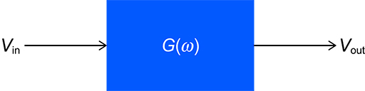
A sinusoidal input signal with amplitude is applied to the filter, and the output is a sinusoidal signal with amplitude . The voltage gain of the filter at the frequency in question is – in other words, it is the ratio of the output voltage amplitude to the input voltage amplitude. So, at any particular frequency,
The voltage gain can be expressed simply as a number or fraction (or decimal). For example, a gain of 2 means that the output amplitude is twice the input amplitude. A gain of (or 0.25) means that the amplitude of the output is one-quarter that of the input.
The above gain is referred to as ‘voltage gain’ because gain is sometimes expressed as a ratio of output and input powers. In this course this way of expressing gain will be referred to as power gain. As power ratios can be expressed in decibels, so power gains are almost invariably given in decibels.
For the time being you will only consider sinusoidal inputs and outputs, as these have a single frequency. This limitation to a single frequency helps to clarify what a filter does. In practice, though, a filter would typically operate on a complex waveform consisting of many frequency components. In such a case, the inputs and outputs would themselves be functions of frequency.
Although two different types of gain have been mentioned (voltage gain and power gain), you will often just see the word gain used by itself. If the gain is given as an ordinary numerical value (such as 2, 10, 3000 or 0.001), voltage gain is almost invariably indicated. If the numerical value is in decibels, power gain is being represented.
The output of a filter differs from the input not only in amplitude but (usually) also in phase. You will look more closely at the question of phase later in the course. However, for now you will continue to focus on gain. Complete Activity 1 to test your understanding so far.
Activity 1
- a.A passive filter has an input signal of volts. The steady-state output is volts. What is the gain as a voltage ratio?
- b.The input to the filter in part (a) remains unchanged in amplitude, but its frequency changes. The steady-state output is now found to be volts. What is the new gain as a voltage ratio?
Answer
- a.Here , the amplitude of , is 10 V and , the amplitude of , is 2 V. Therefore the gain is , or 0.2.
- b. is still 10 V and is now 5 V. Therefore the gain is now , or 0.5.
In the next section you will discover the characteristics of an ideal filter.