

3 Digital signal processing
Digital signal processing has developed rapidly over the last 50 years: digital signal-processing circuits have become faster and cheaper, and memory storage capabilities have increased dramatically. One result of these developments is a migration from analogue to digital circuits for some types of signal processing, and digital filters are an example of this trend.
Digital filters have some advantages over analogue filters. They are programmable, so their operation is determined by a program stored in a processor’s memory. This means a digital filter can easily be changed without affecting the hardware. Also, digital filters are extremely stable with respect to both time and temperature. For complex filters, the hardware requirements are relatively simple and compact in comparison to the equivalent analogue circuitry.
The design of a digital filter is complicated and involves quite advanced mathematics, so software tools that produce a filter design from your specification of filter characteristics are commonly used. However, as you may know from the use of software tools such as circuit simulators, you need to be very wary of using a software design tool to create circuits without having a good understanding of the electrical characteristics of the circuit that you want to create and the parameters used in the design process. A good understanding of how digital filters work will help at every stage of filter design.
For the remainder of the course you will find out about various aspects of filtering a signal digitally. First you will see how a continuous-time signal is converted to produce the digital discrete-time signal used as input to the filter. Then you will find out how mathematical operations applied to the discrete-time signal can remove or diminish unwanted aspects of the signal.
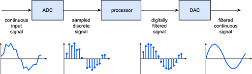
To get started, Figure 13 shows the basic set-up of a digital filter. Don’t worry too much about the detail at this point – it will be covered later. As part of the filtering process, the continuous input signal must be sampled and digitised using an analogue-to-digital converter (ADC) to produce a sampled discrete signal. The resulting binary numbers, representing successive sampled values of the input signal, are transferred to the processor, which carries out numerical calculations on them. These calculations typically involve multiplying the input values by constants and adding the products together. If necessary, the results of these calculations, which now represent sampled values of the filtered signal, are output through a digital-to-analogue converter (DAC) to convert the signal back to continuous form. Given that the continuous input signal and the filtered continuous output signal are continuous in time, they are often referred to as continuous-time signals. Similarly, the sampled discrete signal and the digitally filtered signal are often referred to as discrete-time signals. (Here the word ‘discrete’ means ‘consisting of separate parts’ as opposed to the word ‘discreet’ which means ‘unobtrusive’).
In the next section you will see an example of a digital filter being used as part of a medical system to illustrate the component parts.