
2.2 Gain functions of ideal filters
Figure 5 shows some common types of ‘ideal’ filter. Ideal filters are sometimes characterised as ‘brick-wall’ filters because graphs of their gain functions have perfectly horizontal or vertical lines. In practice, such brick-wall gain functions can never be achieved.
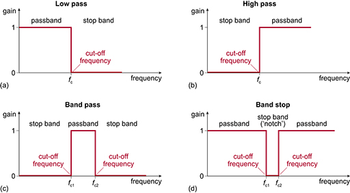
Notice that each of the four types of filter has a name summarising what it does. For example, the low-pass filter (Figure 5(a)) passes all frequencies below the cut-off frequency and blocks all frequencies above it.
In all the filters, a frequency band where the signal is passed is called a passband, and a frequency band where the signal is blocked is called a stop band. All the filters in Figure 5 have one or more passbands, one or more stop bands, and one or more cut-off frequencies.
In all the passbands shown, the voltage gain is 1, but this is a convention for this type of diagram. The actual passband gain depends on various factors such as whether the filter is passive (that is, consists only of passive components, such as resistors, capacitors and inductors) or active (that is, includes amplification as well as passive components).
Similarly, all the stop bands are shown with a voltage gain of 0. In practice, the gain is likely to be above 0. However, provided the stop-band gain is several orders of magnitude below the passband gain, the term ‘stop band’ is reasonable.
In the next section you will see what is meant by interference and noise, which is what is trying to be removed from a signal using a filter.