Bridge girders
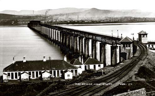
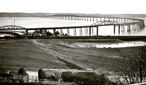
Figures 11 and 12, below, are photographs of the bridge taken from the south and north banks of the firth.
The girders of the bridge were supported on a total of 85 piers. The first 14 piers were made from brick and masonry, built up as a solid structure. The rest were fabricated from iron on masonry platforms, and by comparison, appeared rather insubstantial (Figure 11). Over most of the bridge, the track ran on top of the girders (Figure 12).
But between piers 28 and 41 the construction was different. This was the place where the navigation channel lay, and where the bridge had to have the full headroom of 88 feet. To achieve the extra height, the piers were extended to bring their tops up to the level of the tracks.
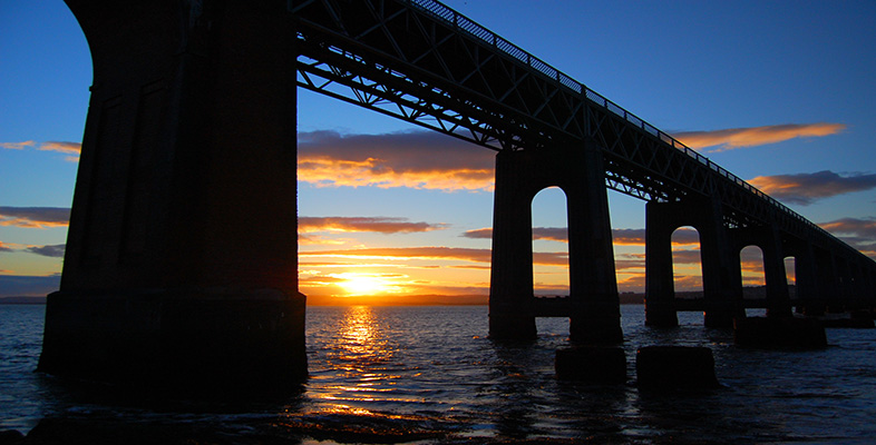
Thirteen spans of lattice-work box section were then placed end-to-end on top of the piers, and the track was carried on the floor of the box (Figure 13). The thirteen spans, the high girders, can be seen clearly in Figure 12.
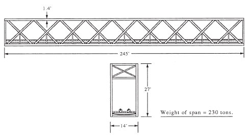
Made from wrought iron sections riveted together, a single 245-foot span weighed about 230 tons complete with track and wooden decking. As shown in Figure 10, the individual spans in the high girders were joined together into three continuous lengths, one of five spans, the two of four spans. The high girders were fixed at only three points to the piers (labelled F in the figure), roller bearings at the other piers allowed for thermal expansion and contraction.
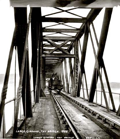
The track was single, laid to the standard gauge of 56.5 inches and fitted with railings on the approach to the high girders. They would not have prevented the train toppling over the edge if it had derailed, however. A passenger would have felt more secure once the train had entered the high girders, although some complained about the drumming noise the open latticework set up as the carriages passed.
Figure 14 shows the side and end elevations of a 245-foot span from the high girders. The main dimensions are given in the Board of Trade (BoT) enquiry report, and details have been estimated from photographs taken for the enquiry.