

1.3 Modelling motion with non-perpendicular vectors
The example of Alice and Bob pushing a block of ice was made simpler by the fact that they were pushing along horizontal and vertical vectors. Let’s look at another example, where the vectors are in arbitrary directions.
Consider the situation in Figure 8, where Alice and Bob have attached ropes to a face of the block of ice and are now pulling it in different directions. If Bob pulls with a force of 130 N at an angle of 47° clockwise from the horizontal, and Alice pulls with a force of 110 N at an angle of 24° anticlockwise from the horizontal, what is the combined force applied to the block, and what is the acceleration of the block?
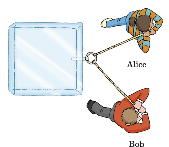
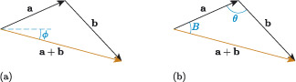
As before, let’s start by creating an abstract drawing, with Alice and Bob replaced by arrows, as illustrated in Figure 9(a). Here, represents the force applied by Alice and represents the force applied by Bob. The vector has a magnitude of 110 N and a direction with an angle of 24° measured anticlockwise from the positive -axis, while has a magnitude of 130 N and a direction with an angle of , measured clockwise from the positive -axis.
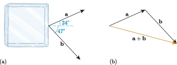
Now, let’s calculate the magnitude and direction of the resultant vector . Figure 9(b) shows the result of visually adding the vectors and . Unlike the previous example, and are not perpendicular, so the triangle formed by , and the resultant is not a right-angled triangle. In this case, we cannot use Pythagoras’ theorem or the trigonometric functions to calculate the magnitude and direction of , and instead we need to use other properties of triangles, such as the sine or cosine rules.
If we knew one of the interior angles, then we could use the cosine rule,
to calculate the magnitude of from the magnitudes of and , as follows:
where is the interior angle opposite , as illustrated in Figure 10(a).
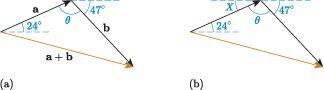
To find we can make use of alternate angles (Z-angles). The angle in Figure 10(b) is an alternate angle with the angle indicating the direction of vector , so . Also, , and the angle indicating the direction of vector all lie on a straight line, so
Using this relation, we can now find the size of angle , and use this in the cosine rule to determine the length of .
Activity 4
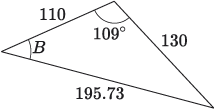
Use the cosine rule to determine the length of edge in the diagram below, to two decimal places.
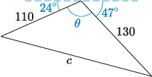
If we apply our answer to Activity 4 to the vector diagram in Figure 10, then we have calculated that the magnitude of is approximately 195.73 N. The direction of is given by the angle in Figure 11(a).
We already know that the direction of , so if we can find the angle in Figure 11(b), then we can calculate from
We can calculate using the sine rule,
as follows:
Activity 5
Use the sine rule to calculate angle in the diagram below, to one decimal place.
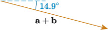
From Activities 4 and 5, we can therefore say that, approximately, the magnitude of is 195.73 N and its direction is given by the angle
which is measured clockwise from the horizontal, as illustrated in Figure 12. This is the combined force applied by Alice and Bob to the block of ice.
Activity 6
A block of ice has a mass of a metric tonne (), and the resultant force on the block is described by a vector with a magnitude of 195.73 N and a direction of 14.9°, measured clockwise from the positive -axis. Give the magnitude of the acceleration to two decimal places and the direction to one decimal place.