

Background
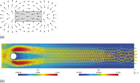
It is common in engineering for physical phenomena to be represented as vector fields. A vector field is a mathematical representation of a system that describes how a quantity, such as a force, changes over an interval of time, or an area or volume of space. Figure 1, for example, illustrates vector fields created by magnets (in part (a)) and fluid flow (in part (b)). A vector field can be thought of as a graph where every coordinate has not only a position, but also a magnitude and direction. In the images in Figure 1, these are represented by small arrows, with each individual arrow indicating the direction and magnitude of a force at a specific position.
When viewed as a collection of individual vectors, vector fields can be very complex and difficult to understand, but when viewed holistically, patterns emerge that give insight into physical phenomena.
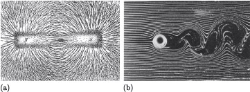
The examples in Figure 1 result from mathematical models, but accurately reflect the real-world situations they model. The first image is a diagram showing the magnetic field generated by a bar magnet, and accurately reflects the patterns created physically by iron filings when acted on by such a magnet, as illustrated in Figure 2(a). The image in Figure 1(b) is the result of a computational simulation of the fluid flow around a submerged cylinder, and is a representation of the real-world situation illustrated in Figure 2(b), which was created by smoke filaments in a wind tunnel. This representation is less accurate, with a difference in the flow to the right of the cylinder: in the physical example the smoke filaments become turbulent and messy as a result of the vortices formed in the wake of the cylinder, but in the simulation the flow remains smooth. This difference is a consequence of assumptions made in the mathematical model describing the flow. Assumptions have been made to make the mathematics more manageable by neglecting the complexity that gives rise to the vortices.
Vector fields are beyond the scope of this course, but you are likely to encounter them if you decide to take this area of study further. In preparation for this we will explore the mathematics of vectors.