
3.8 Forming our gearwheel
We have just seen that simple 2D 'linear' objects can be produced by rolling, drawing or extrusion. So could our gearwheel be made using these techniques?
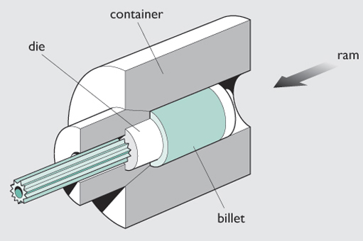
Because the gearwheel has a constant section it is geometrically feasible (actually the section is not quite constant because it is countersunk on one side, but let's ignore this fine detail for the purpose of this discussion). Drawing is confined to small reductions in cross-sectional area during each pass, so this process does not look promising, but there is no such limit on extrusion. By extruding a deformable material such as metal or thermoplastic through a bridge die containing a gear-shaped hole and a square bridge it should be possible to produce a very 'thick' (or long, depending on how you want to describe it!) gearwheel (see Figure 35). This can then be cut up into identical gearwheels of the required thickness, so this might be a possibility.
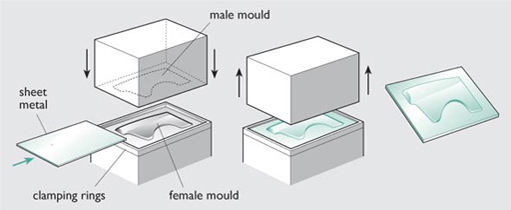
Would rolling be an alternative manufacturing process? It would be difficult to roll the gear teeth profile, but you could use rolled steel sheet as a starting material. You could then punch out a gear-shaped blank using sheet metal forming (Figure 36). This would be expensive, but is possible.
However both extrusion and the sheet-metal route would produce flow lines not suitable for an engineering gear, as described in Failure of replacement gears.
So let's go back to our gearwheel again and decide whether a gearwheel can be made by forging. The answer is yes, but only partly. Some other processing would be needed either before or after the forging process.
One approach is to start with steel bar (itself produced by rolling between contoured rolls). The bar contains longitudinal flow lines in its microstructure, produced from the rolling operation. This bar is forged into a circular, gear-sized, disc by compressing the bar parallel to its length (Figure 37).
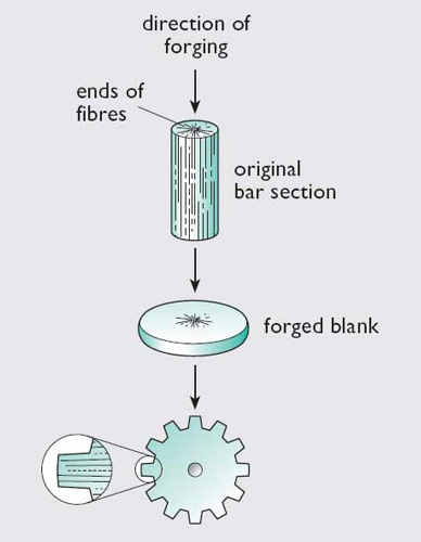
The forging 'folds over' the longitudinal flow lines into the radial direction. So in this case, all the gear teeth have the optimum orientation of flow lines and the final product is stronger than that made from rolling. Failure of replacement gears describes why the microstructure of gears can be of critical important to their performance.
SAQ 7
Which of the processes (including both casting and forming) covered so far would be the most appropriate to manufacture the following products? Use the shape hierarchy for both casting and forming to help guide you through some of the options.
-
A church bell.
-
Aluminium foil for food use.
-
A plastic beaker.
-
The plastic body of a food mixer.
-
Copper pipe for use in plumbing.
-
A shaft for use in a car engine. (Hint: the component is manufactured from solid steel. The shaft requires high strength for this application. Think about its shape – I would classify it as non-complex.)
Answer
-
Whilst it might be possible to forge a bell, the tooling would be very costly for a one-off, so sand casting is the best option here.
-
A sheet-like shape such as this would be made by rolling, using progressive reductions in the sheet thickness.
-
A plastic beaker could be made by injection moulding.
-
If the body is to be made of plastic then injection moulding would be the only choice. This is a process which can produce complex 3D shapes.
-
The pipe is a simple 2D shape, so could be made by extrusion using a bridge die.
-
For high strength, forging is better than casting. As the component is solid and the shape is non-complex, closed-die forging would be used.